Overview
In my last blog on pfSense, I covered how to try out some of the basic firewall functionality of the FreeBSD-based firewall. However pfSense is more than just a firewall, it can act as a router and support functionalities such as those of a loadbalancer and a failover. It even has package support for SquidProxy web cache, and VPN technologies such as IPSec and OpenVPN. In this blog, I will show you how to go about playing with some of these features of pfSense on your own.
The functionalities that I will cover in this blog are :
- Configuring pfSense as an internal load balancer.
- Configuring pfSense as a SquidProxy web Cache
- Configuring IPSec (site-site) tunnel mode in pfSense.
Prerequisites
It is expected that you have the prerequisites mentioned in the last blog. Also, you should have an installed copy of pfSense on FreeBSD. Netgate offers a direct pre-pfSense installed version of FreeBSD OS. This blog will go over some of the concepts of IPSec, but not too deep in the conceptual parts. I will post some links at the end for you guys to get a hang of IPSec. Also, a basic understanding of networking concepts such as routing and gateways will come handy to understand some parts covered in this blog.
Section:1 pfSense: As a load balancer
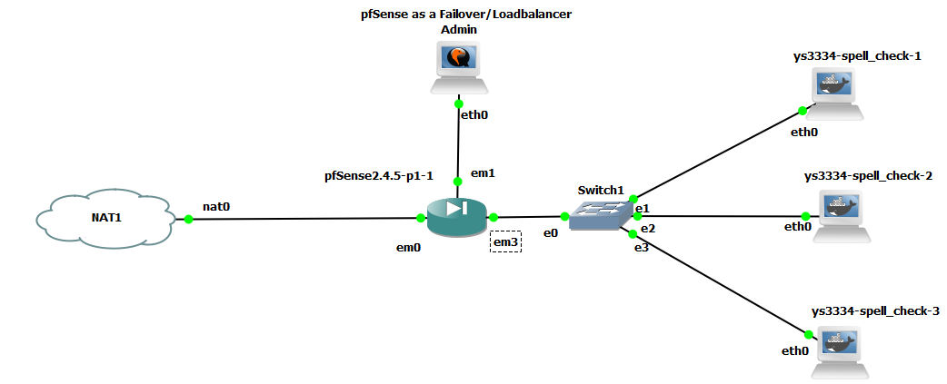
pfSense can act as a load balancer for your webservers. The setup involves setting up the pfSense before the webservers on a subnet and loadbalancing them. The Setup shown in GNS3 in the image below involves the following assets. The purpose here is to balance or schedule incoming web requests or inbound traffic to one of the web servers in a round-robin fashion.
- GNS3 VM or GNS3 running on server
- Web server or containers for web servers. Here I used a container I created for another project. If you want, you may use the same container image which runs a web server on port 5000. Note however, that session persistence is not managed by the pfSense loadbalancer, and has to be done externally.
- pfSense on FreeBSD and one machine for accessing and administering the pfSense using the web GUI.
 |
|---|
| Image-1:pfSense GNS3 loadbalancer setup |
Setup and Implementation instructions
- Make sure pfSense is configured to be reachable via the Admin machine / Web GUI is accessible.
- Configure the containers for GNS3 or the web servers to be on the same subnet. The “em3” interface connected to the subnet containing the webservers could be configured to use a DHCP. In this case however, it is preferable to have them statically configured as the IP addresses will need to be entered into the load balancer pool.
- Check if you can ping the “em3” interface of the pfSense from the webserver machine, or ensure in any other way that you have network connectivity to each of the web servers/containers.
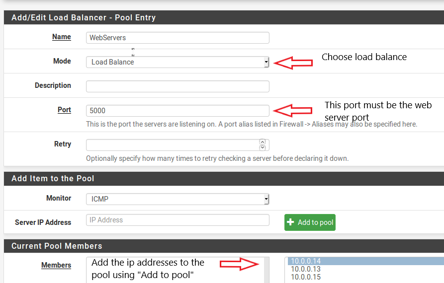
- In this scenario we have 3 web server containers. We have IP addresses 10.0.0.a, 10.0.0.b, 10.0.0.c for each of the web server containers. The em3 has the ip address in the same subnet at 10.0.0.1.
- Click on Services->Load Balancer->Pools from the Web-sense GUI. Add the webserver Ip’s to the pool as shown below.
 |
|---|
| Image-2:Create the virtual server pool |
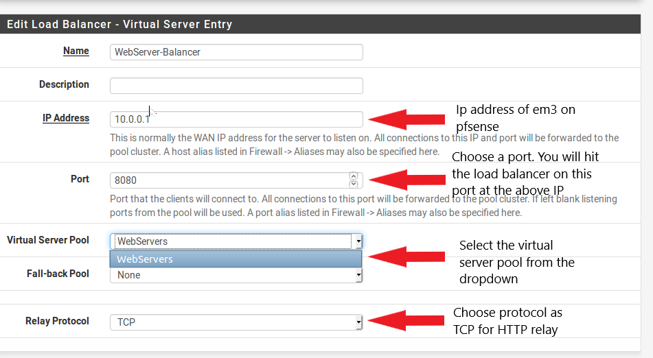
- Once this is done we need to configure the load balancer and mention the port it will listen to. The load balancer will be listening on this port for incoming request to the webservers, and load balance them among the Ip addresses mentioned in the pool above. This is shown below, and done from the menu Services->Load Balancer->Virtual Servers .
 |
|---|
| Image-3:Add the server pool to the load balancer |
- Once all is done, save the changes. To see if the webservers are up and running, hit the IP address first for each webserver at 10.0.0.a:5000/10.0.0.b:5000/10.0.0.c:5000. If they work, try hitting the load balancer. The load balancer will forward and select a web server in round robin fashion. Hit the load balancer at 10.0.0.1:8080, where 8080 is the port you configured at the virtual server menu above.
Section 2: pfSense as Squid Proxy Server and Web cache
pfSense can act as a web cache and transparent proxy to reduce bandwidth usage on outbound internet traffic with package support of Squid Proxy. SquidProxy is a web cache based on the harvest cache daemon and has been around since the 90’s. A lot of firewalls configure SquidProxy for caching web requests and also restricting access to certain domains, keeping track of viruses , and network layer restriction on internet access etc.
You would need a OS with browser and access to the internet intercepted by the pfSense , and an admin machine (optional) for administering the pfSense. You could use 1 machine for both the purposes as well.
Setup and Implementation instructions
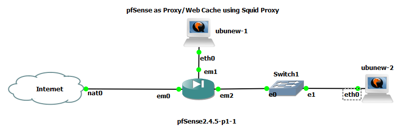
- We need pfSense setup with any one or more of the Lan interfaces. If you are creating an additional interface for testing the proxy, make sure you allow the traffic in like specified in Lan (em1) rules by default. For this setup I used a separate interface and subnet outside the default Admin Lan interface for testing out pfSense as shown below.
 |
|---|
| Image-3:Network Layout Squid Proxy |
- Before you go ahead, install the squid proxy package into the pfSense. This can be done from the WebGUI. Select System->Package Manager->Available Packages. You can search for squid proxy package from the search bar and then install it.
- Once installed, it should show up in the installed pacakges.
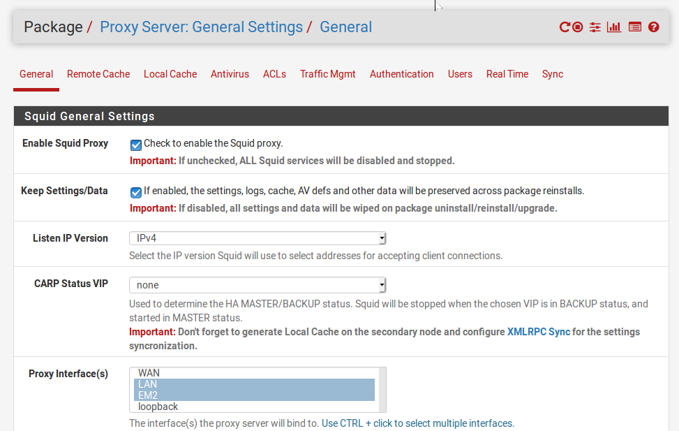
- Once it is done, we can configure it from Services->Squid Proxy Server. Make sure you enable the server, and add the interfaces on which the proxy server will enabled as shown in the image below.
 |
|---|
| Image-4:squid proxy settings and server |
- If you plan to enable SSL filtering, make sure you generate your own CA certificate from pfSense and install it in the browser so that the SSL certificate is properly authorized by pfSense.
- For system optimization such as cache size, in memory cache size and RAM size, and object size for in memory caching, go to the **Local Cache ** tab.
- You can enable ClamAv and Safe Google browsing for Squid Proxy in Local Cache.
- The other important settings comes under the tab ACL’s where you can allow different subnets, and block and allow different domains. Note that if you block domains with “https” , you need to enable SSL filtering and install your self-signed certificates in browsers.
Section 3: pfSense as IPSec site to site VPN (tunnel)
pfSense has built in GUI support for VPN technologies like OpenVPN and IPSec. I earlier intended to cover the OpenVPN part, but then felt would be too long for this blog, so I may cover it later. This one is going to get a bit long and tedious on its own. The IPSec protocol is used widely for secure communication over the internet. The idea is used widely in corporations where one local network or site needs to co
While I would love to elaborate more on how IPSec , this blog will get too long if I continue on that road. IPSec in a grossly simplified way provides a way of securely communicating by providing encryption at the Network layer. The IPsec in tunnel mode encrypts the original IP header and the devices in between the 2 gateways see the traffic with the IP headers added by the 2 gateway devices. So any device sending a packet from site A to site B will be encrypted by the 2 gateways and sent, and the devices on the internet will see the gateway IP headers instead of the original one. If you are confused, as to what tunnel mode is , please go through this link below for further clarity. It is important to understand conceptually what we are doing, before going ahead and performing the steps.
Links
I stress this because once the concepts are clear, what we do through the GUI , and the commands we execute make sense and becomes second nature.
Network setup
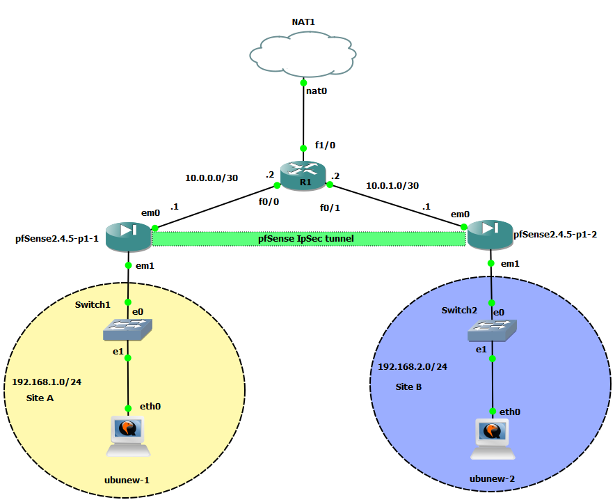
- The minimalistic network layout for this exercise requires more network experience than previous endeavours. The topology looks like what is shown below.
 |
|---|
| Image-5:Network Layout for IPSec site to site (tunnel) |
- So , let’s explain the involved devices used and their functionality:
- Two instances pfSense with FreeBSD. These will be used as the 2 VPN gateways for the 2 sites. In Site to site tunnel mode, the 2 sites cannot have overlapping subnets. The reason is we need the devices in each of the sites to treat the pfSense devices as gateway.
- The router sits in the between in this layout represents a device on the internet and provides connectivity between the 2 gateways. You may choose an FRR based router, or a Linux OS with forwarding enabled. I chose a ciscoIOS router here.
- There is one machine in each of the local sites which are Ubuntu based OS, and also used to administer the pfSense firewall in their respective sites.
- The NAT device is for giving the pfSense firewalls access to the internet, you may choose to skip it to avoid complications, and that will not interfere in this exercise.
- Let’s configure the various interfaces on each of the devices. The device in the middle has two interfaces each in the broadcast domain/subnet of interfaces of each of the site.
-
The pfSense has 2 interfaces up by default. The WAN (em0) which usually we connect to internet facing subnet, and the Lan interface (em1) used for administering and configuring itself via the WebGUI.
-
We will connect the WAN interfaces (em0’s) to the router R1 for each of the pfSense, and the LAN interface is the interface taking part in the subnet for each of the sites.
-
-
The LAN interfaces will have to be configured so that they are on different subnet space. Note that by default pfSense has a 192.168.1.0/24 subnet configured on em1 (LAN). So for site A leave it as is, change the configuration for Site B’s DHCP. For the corresponding machine “ubunew-2” needs to relinquish the IP if already assigned. The following is a way to do that.
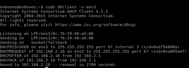
Image-5:DHCP forced renewal The next step is to configure the interfaces connecting the router to the pfSense. Since only 2 machines are present here, we may use PPP here . I went ahead and configured it via LAN. Here I used a /30 subnet . For siteA’s pfSense, I used 10.0.0.0/30 and for siteB’s pfSense 10.0.1.0/30. Note that the ping check might fail due to firewall rules.
-
Next thing we want to see if the pfSense on site A can ping the router’s interface connected to Site B’s pfSense. For this we need to make sure we configure the gateways and route. This means we need to tell pfSense on site A, that there is a path to 10.0.1.0/30 via R1. We need to do two things on each of the pfSense machines. 1st would be to configure a gateway, and then configure a static route via this created gateway. The following image shows it (You need to do it on the other pfSense machine accordingly). I have shown the steps below for site A pfSense, reciprocate it on the other pfSense as well. Go to System->Routing from the Web GUI Once this is done configure a static route to use the newly created gateway as shown in the next image.
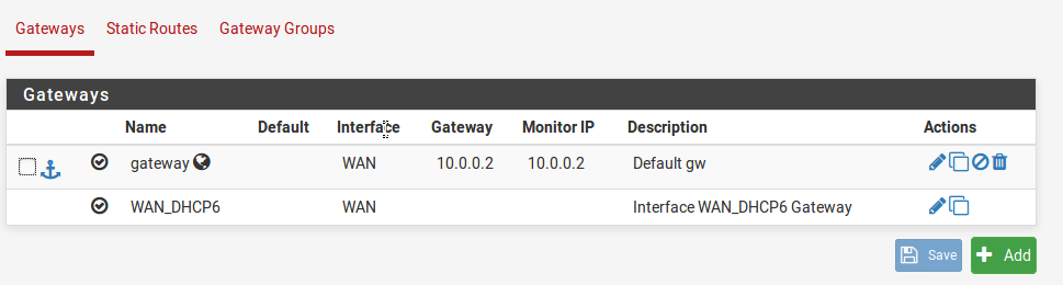
Image-6:Create a gateway for the next hop 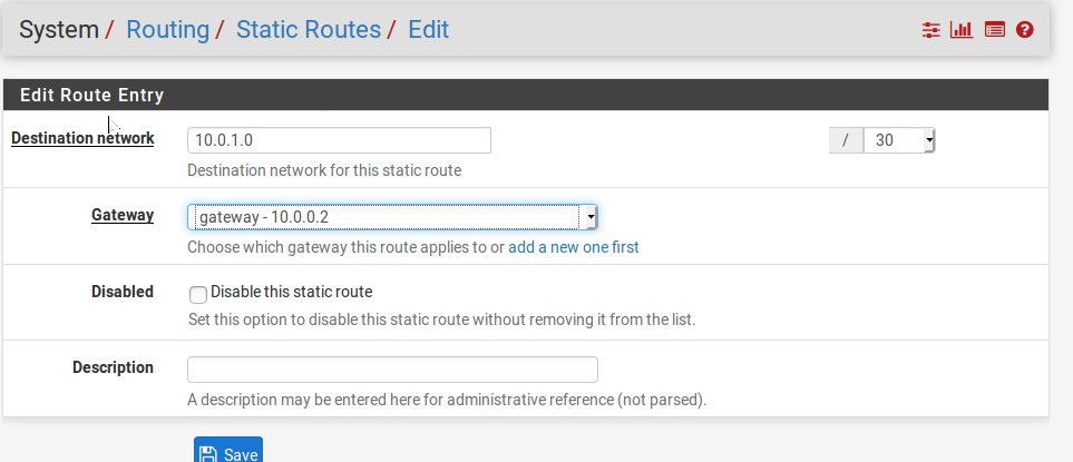
Image-7:Create a static route to use this newly created gateway -
Next we need to do the IPSec stuff. Note that I show this only for site A, but you will have to repeat the steps for the Site B’s pfSense for the IPSec to work. An important thing to note here is that R1 does not need to know what to route or the local subnets as the tunnel mode will prevent R1 from seeing the actual IP headers. So R1 does not need to know or configure routes to and from the site subnets.
-
Let’s move on to the VPN part. So for IPSec we have 2 phases. In phase 1 , we configure the security mechanisms such as encryption ,hashing algorithms and authentication to be used for the VPN configuration. This is an agreement between the 2 parties taking part in the IPSec VPN connection. For configuring phase1 feel free to choose the methodology, but keep the configuration more or less the same on both the pfSense. Below shows what I performed on both the pfSense. To access IPSec settings, go to Services->VPN->IPSEC
-
Then, click on add p1 which refers to phase-1. Here configure the key-exchange version as IKEv2, interface as WAN, and the remote gateway IP. For pfSense at site A this must be the IP address of the WAN interface of pfSense at site B. The next thing would be to choose authentication method as Mutual PSK. Set a password, this needs to be same on both the pfSense. Before you save and apply the changes, make sure you go to the Advanced Settings tab and enable the Enable MSS Clamping on VPN traffic. Verify and save the changes.
-
We need to next configure phase-2. Once you have configured phase-1 you will see an option to add phase-2 below it. This is under Services->VPN->IPSec->Tunnel. Click on add p2. The for the local site subnet mention the subnet address or alternatively the interface whose pfSense you are configuring. For the remote network configure the remote site’s subnet as shown(site A pfSense).
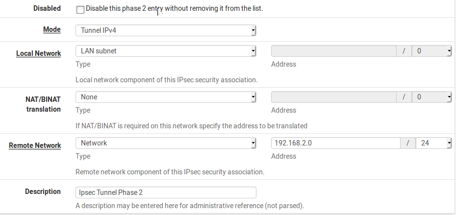
Image-8:Phase-2 configuration for IPSec VPN -
In the settings that follow, set the authentication and encryption mechanism in accordance to what you selected for phase-1.
-
Once you have done the steps above for both the sites and pfSense respectively, we need to create firewall rules for exclusively allowing traffic via the pfSense. In pfSense you can actually set rules specific only to the IPSec interface. This again needs to be done on both the pfSenses. Following shows the rule for pfSense at site A. Go to Firewall->Rules->IPSec. (This will only appear once you have the phases configured). I have for simplicity sake allowed all traffic on IPSec, you may be more restrictive in what you lay down.
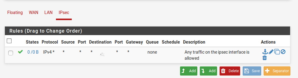
Image-9: Firewall rules on IPSec interface -
We need to remove the default block rules on the WAN interface and allow traffic for the ISAKMP protocol so that the VPN connection may be suitably established. So the first thing we need to do for both the pfSense’s WAN interface is to remove the factory rules. Now we need to allow ISAKMP traffic (UDP 500) as shown below.
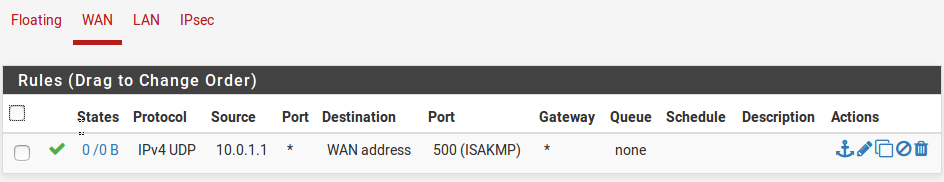
Image-10: Firewall rules on WAN interface -
The next thing is to go ahead and save the rules. Make sure you have done so for both the pfSense. Once this is done, you can establish the VPN connection by going to Status->IPSec->Connect. If you have configured everything correctly, you should see an established connection on the status tab. Moreover, ubnew-1 can now ping ubnew-2 (Site - site connectivity in tunnel mode)
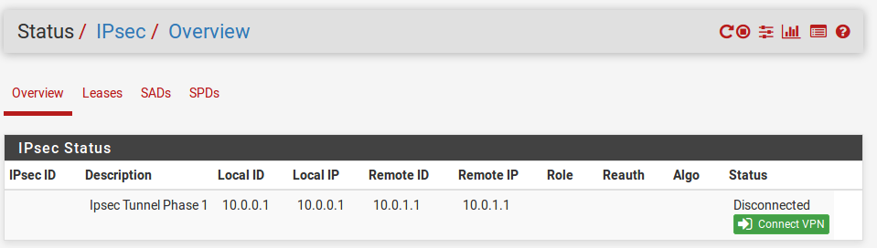
Image-11:Connect the VPN
If you get stuck or have queries please use the comment section to reach out to me, I will try to help out to the best of my abilities.