Exploring Pf-sense Firewall, Part-1
Overview
Open source stateful firewall/software based on the free BSD OS. It is open source, and hence a lot of users and developers trying to learn firewalls choose this. Pfsense can be manually installed on FreeBSD, but we can get a pfsense preinstalled FreeBSD iso from the website.
These notes are for my personal reference on the pfSense firewall, but I thought I should share these in case anyone else has the same confusions and also to avoid common pitfalls. I come from an “iptables” background, where we know the context and terminology is clearly L3 or Network layer. Hence , I have had little confusions with regards to iptable rules. The faint-hearted should not glance at the iptable chain and netfilter diagram, or else that person might give up on learning IPtables entirely - If you do not believe me, have a look here. That being said, the terminology of pfSense and the rule structure, and some of the implicit behaviour threw me off a lot.
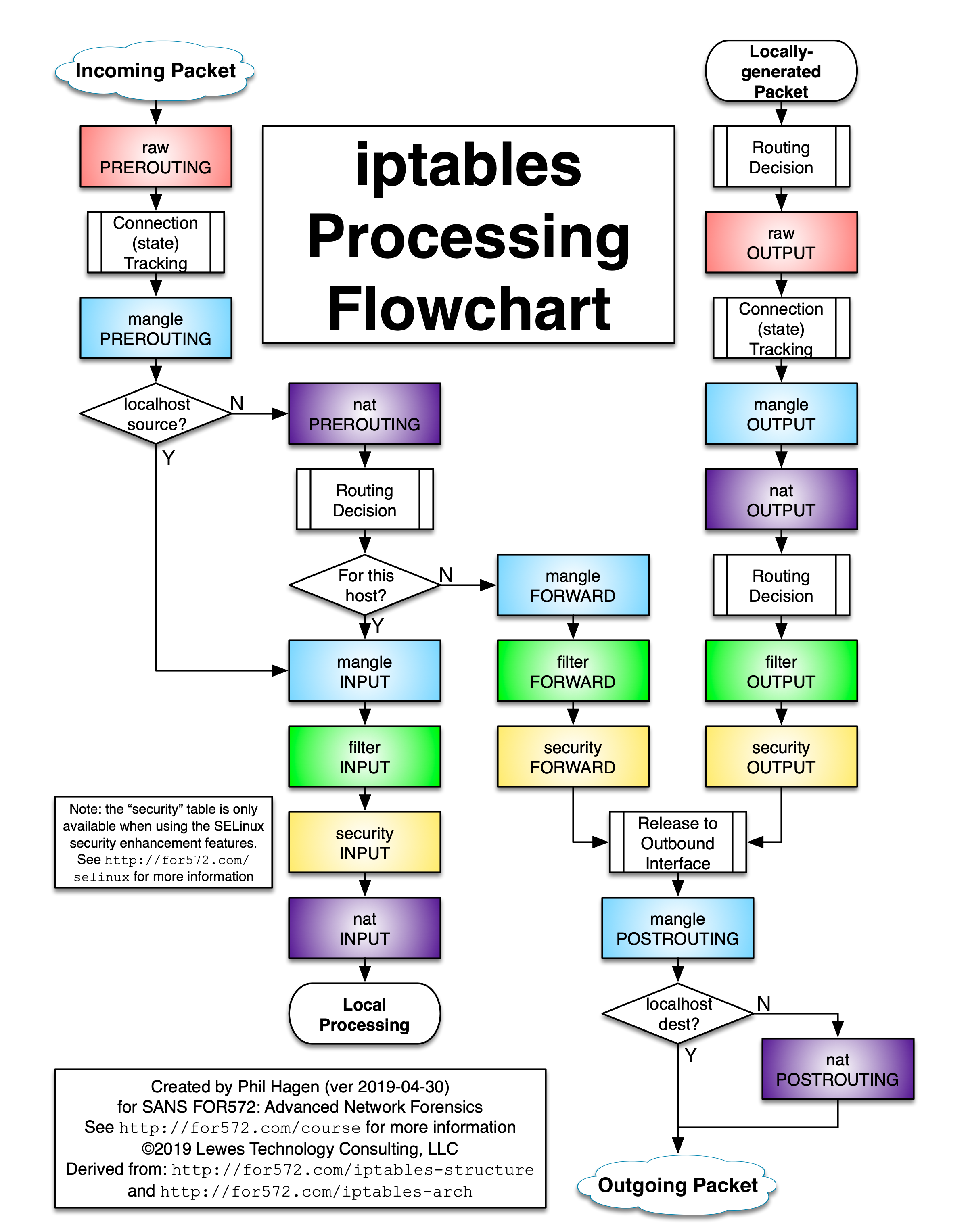
In this section, we will explore how to setup a basic working network environment for pfSense, and configure some run-of-the mill firewall rules.
Pre-requisites
Basic understanding of network concepts and lingo such as packet headers and OSI layers. I would say some prior experience with a different firewall comes in handy but not required.
Setup and Config
For the setup, using GNS3 , the awesome open-source network simulator. We will be using QEMU based appliances for the entire network, so that we can replicate instances. The pfsense is by default reachable via http on a preconfigured interface with ip 192.168.1.1/24. A dhcp server runs on this interface, and hence a client connected to this iface gets the IP assigned automatically.
Use the setup wizard to setup the WAN interface which is for internet access for the pfsense. The setup option allows you to setup pfsense and configure some of the basic stuff like dns nameserver settings etc.
You may configure and add different users and specify privileged and unprivileged roles. You can also configure the different types of ports for reaching the Web gui among other stuff.
DHCP config
The dhcp server may be configured from the dashboard Services> DHCP server. Here you can do typical dhcp server stuff such as ip range config, blocking IP’s, assigning and reserving static IP’s etc and assigning default gateways to client. You can configure dhcp servers on other interfaces by Services->DHCP and then selecting the correct interface.
Important note related to interface config:
The interfaces em0 and em1 or lan0 and lan1 are present and configured by default on the pfsense firewall. The em0 or the WAN interface is defacto configured as the gateway that you would expect to be connected to a dhcp server or gateway. This would be the interface connecting the pfsense to the internet.
By default lan1 is used to configure and administer the firewall, and has dhcp server running. The default gateway is configured as lan1. The pfsense forwards the packets (from Lan-1) out the WAN interface which has the default gateway. Basically, the default route pfsense uses to forward packets is via WAN interface.
 |
|---|
| Image-1:pfSense acts natively as a router with firewall capabilities |
Pfsense as a firewall
Rules configured for each n/w interface. Embed the following line from the documentation in your memory regarding pfsense
“Firewall rules on Interface and Group tabs process traffic in the Inbound direction and are processed from the top down, stopping at the first match. Where no user-configured firewall rules match, traffic is denied”
So whenever you add rules on an interface keep in mind that you are applying it to the inbound direction of that interface. This means to all traffic “arriving at the interface”. For people familiar with iptables , this means only packets coming to the interface (INPUT and FORWARD). For controlling outbound traffic, we need to specify them under “FLOATING rules” which can apply to traffic in both directions.
Rules follow order. Rules process traffic in top-down order of added rules. It stops at the first rule it matches. By default it has an anti-lockout rule configured so that access to GUI is never lost.
From the documentation “pfSense is a stateful firewall, which means it remembers information about connections flowing through the firewall so that reply traffic can be allowed automatically. This data is retained in the State Table. The connection information in the state table includes the source, destination, protocol, ports, and more: Enough to uniquely identify a specific connection.”
There are 3 action types “Allow, Block and reject”. Reject is a block wherein the sender is notified of the packet drop.
 |
|---|
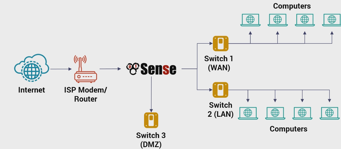
| Image-2:Default rules on the LAN(em1) interface |
Typical rules in pfsense firewall look like above.
You have multiple options at TCP state-level for configuration.
Some of the fields such as Source, Destination are self explanatory. They can take interface addresses or subnet ranges . “{Interface-Name}”-Net and “{Interface-address}” are specified. Interface net matches anything in the subnet range configured for that interface, and Interface-address matches only pfsense’s interface address.
Making sense of rules
There are some rules which are present by default like “The Anti-lockout” rule which is explicit but cannot be replaced from top of the list. The default behaviour for all inbound traffic to an interface is deny as stated in the documentation.
There are few lines which can lead to some confusion in the initial stages. It is easy to forget often, that the interface rules and rule groups are applicable to “inbound traffic” only.
These lines in the pfsense documentation especially confused me, and can confuse others too.
In a default two-interface LAN and WAN configuration, pfSense utilizes default deny on the WAN and default allow on the LAN. Everything inbound from the Internet is denied, and everything out to the Internet from the LAN is permitted. -Concept (1) as specified in the documentation.
First the term “inbound” and “outbound” traffic could mean differently for connection oriented vs stateless protocols like UDP. For stateless protocols outbound and inbound traffic mean exactly the literal sense of the word. Packet leaving the interface referring to outbound traffic, and packet reaching the interface would be inbound traffic(destination as interface) and outbound traffic is packets leaving the interface (source as interface)
The connection oriented version of the interpretation is that, the inbound traffic means connection was initiated by the outside source and the outbound means connection was initiated from the inside.
An important determination here is what is “inside” vs what is “outside”? As this very definition is woven into the concept of what is inbound and what is outbound.?
Remember the firewall rules applied to inbound traffic. This is determined from the point of perspective of the interface and not the firewall. For eg: Take eg: Outbound traffic from LAN to WAN-> Traffic leaving the lan for the internet via the WAN. Remember however, that for the LAN interface this is (DST mac address is LAN interface) inbound traffic, and for the WAN interface this is outbound traffic (src Mac addr WAN iface , DST MAC addr not WAN iface) .
Important for Iptable folks: thing to understand here is that the term FORWARDING makes sense only at L3 (Network Layer), dst IP is not the iface IP but dst mac is iface MAC implying packet is meant for another target.
Let us now come back to concept 1. Two understand it , 2 things are important to keep in mind.
- If there is no rule match, the default is deny
- The rules apply to inbound traffic only
The default WAN Rule is a block-all rule which means by the above 2 points is that the inbound traffic is blocked completely. And hence the outgoing traffic is not blocked. To control the outbound traffic we need to work with floating rules. This is the reason, the internet access is allowed but outside connections are not allowed in.
For the LAN interface we have 2 allow all rules configured for ipv4 and ipv6 protocols. This means all inbound traffic to the LAN is permitted (initial factory configuration). On the WAN we have a default deny all, which means all inbound traffic is blocked but it has no binding on the outgoing traffic. In the TCP terminology, the inbound traffic refers to the traffic that originated (Initiation of connection) from within the network.
Firewall Rule Structure
While filling out an interface rule via the GUI , the following properties describe the rule being added:
- Action: Block,deny and reject are 3 actions on an incoming packet.
- Interface: The interface is the interface the traffic would arrive into physically
- Source: This is the source address IP header of the packet.
- Address Family, Port, Protocol: Address family refers to the IPv4 or IPv6. The protocol level filtering can only be done on the Network or the transport layer. The port number refers to the destination port number, the source port number cannot be filtered on interface level rules. The traffic at the interface level refers to inbound traffic, so filtering on source port number won’t make sense, as the source port is randomized.
- Destination: The destination address in the IP header of the packet.
The source and interface may differ when an interface receives packets coming from a different IP source in case of NAT or forwarding. Source and destination fields refer to layer 3 headers of the packet. The direction of the traffic the interface rules apply to is “inbound” i.e the packets whose destination L2 header is the one specified by the interface field or in other words, packets which arrive at that interface.
GNS3 setup and implementation
GNS3 was used to setup the network on the remote system as a server.
- Server system specs: 264 Gb of RAM, 40-core CPU. It is extremely over-the top for such a light weight simulation. You can set this up easily on a local GNS3 VM on a 16-Gig ram system.
- GNS3 Appliances: 1x FreeBSD with pfSense, Alpine as end systems for testing the network, and an Ubuntu-VM 18.04 LTS for controlling the pfSense via GUI from a Browser. You can however skip the Ubuntu, and setup connections from the Host VM to the pfSense firewall. FreeBSD default credentials are admin:PfSense
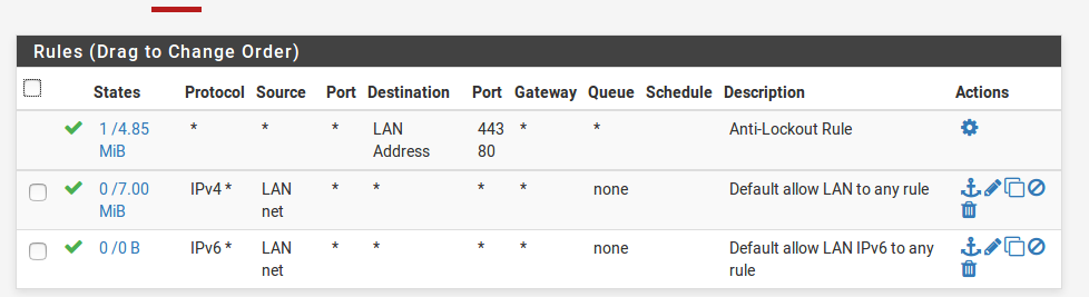
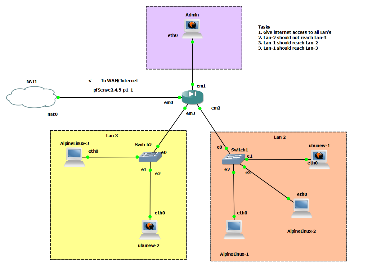
- The network looks as shown below. We have 3 LAN’s . Lan-1 has only the administrative VM. LAN-2 and LAN-3 have additional machines and subnets which do not overlap and have a /24 mask. The Lan and WAN are the 2 default interfaces present on the FreeBSD pfSense by default at the time of writing this. The WAN interface is em0 and the LAN interface is em1. You will notice some default rules present which allow the Admin to have internet as well as default Web GUI access (the Anti-Lockout rule).
 |
|---|
| Image-3:GNS-3 sample network setup |
You can access the web GUI by default at the static Class C address 192.168.1.1 (Static Lan-1 interface address) from the Admin Machine. The Web GUI is pretty standard and is easy to use. By default only 2 interfaces are active on the machine Lan (em1) and WAN (em0). Make sure you have atleast 4 interfaces activated from the template of FreeBSD-pfSense in GNS3. You can do this by clicking on the VM and selecting “Configure->Network” and then increasing the number of interfaces.
Baby-Steps: Basic Firewall Rules
Alert: Note that the default-deny rule of WAN or em0 will allow internet connection for the Admin machine. This is because firstly, the Lan interface has an all allow rule on ipv4 and ipv6 as shown in image-2. This means that it will allow all arriving(inbound) packets at Lan1 from any source to pass through and for any destination. You might then ask “What about the default deny rule on WAN?” Keep in mind that the default deny rule in English terms means this. “Deny all packets which ->arrive<- at the WAN interface, or whose L2 destination is WAN”.
This will not block outgoing packets. It is important to clarify here, as the devil truly is in the details. The TCP traffic is allowed (HTTP uses TCP) - Lan1 controls this part as the traffic is inbound on Lan-1 interface , (L2 destination header ). The forwarding makes the traffic go “out” the WAN interface, and hence not blocked. This is the reason LAN-1 has internet access despite the deny-all rule in WAN.
So the onus of controlling the traffic to the internet rests on the local interface on which the local/subnet traffic is inbound. For the Admin machine, that interface is Lan1(em1)
With the above fundamentals in mind, here’s what we are about to do.
- Configuring DHCP on all the interfaces
- Internet access on all subnets.
- Allowing Lan-2 to reach web servers in Lan-3 but not SSH or any other protocol.
- Lan-3 must be able to ssh into any machine in Lan-2 but not the other way round.
- Lan-1 must be able to access all subnets via all protocols, but the others cannot do so for Lan-1 unless explicitly stated in the rules below.
- The Web-UI must be accessible only via Lan-1 and not by any other subnet.
- Make sure the rules added are minimalistic. Nothing is too restrictive. Everything not mentioned under the rules should be allowed, and not blocked. The rules should not enforce anything not intended or mentioned above.
Setting these rules, would give us a fair bit of idea on how pfSense works as a router and a firewall.
Bringing up interface, configuring DHCP to share some IP’s:
-
Do not modify the default rules, on em0 and em1. Make sure that you can reach the Web GUI via the admin machine (Lan1). Login using the default credentials which are admin:pfsense.
-
Bring up the other interfaces. Make sure you have configured them to be present via GNS3 or whatever virtualization technology you are using. Once that is done, assign them a static IP address. We won’t have a lot of machines in the subnet, but a /24 mask is easier to read and interpret. Note that each interface must have a static IP address, before a DHCP server can be configured on them. Click on Interfaces-> {Interface-Name} and then enable the interface. Assign it a static ip address with a /24 or any proper subnet mask of your choosing.
-
Do this for the 2 interfaces em2 and em3 and do not forget to save and apply your changes.
-
Once this is done, DHCP can be enabled on the interfaces. Go to Services->{Interface-Name}. Enable the DHCP server after selecting the address pool and then apply the changes.
-
For the Alpine OS , you need to change the network configuration for them to request IP from the DHCP servers. This would be the IP address of the interface for each subnet. If em2 has IP X, this needs to be configured as the DHCP server for all the machines in the Lan-2 subnet.
-
For the Ubuntu machines, you can try whether DHCP server is working by doing the following to explicitly request an IP.
sudo dhclient {interface}
Access to Internet for all subnets:
- This is easy to do. For this simply enable the simple rule of all Ipv4 traffic from any source to any destination like what Lan1 has by default. You may add the ipv6 rule as well.
- The rule has the same structure as the IPv4 rule shown in Image 2.
- Check that all machines have internet access via web browser or via pinging.
- The WAN rule will prevent machines outside to initiate HTTP connections with machines in the subnet.
Restricting access selectively
- We will move the default internet rule to the bottom and add selective default block rules at the top so that we achieve what we want. We will add the default allow all Internet rule at the bottom, which is an exact copy of the rule of Lan-1. Adding rules that restrict access will now be added on top of this rule, and when a packet that matches a restrictive rule is encountered, it won’t proceed down the rules as rules are read top-down, and stopped at first match.
- Since Lan-1 does not need to restrict access, the Lan-1 rules do not need to be touched.
- Add the restriction rules on the interface the restriction is applied to. If you need to restrict Lan-2 , add rules to Lan-2, as those rules will control the inbound traffic on the Lan-2 interface.
- So, all said and done these are the rules on each of the interfaces. They work, and they are minimalist. The rules on Lan-1 as mentioned are untouched and depicted by Image-2.
If you get stuck, or have questions feel free to use the disqus comment section.
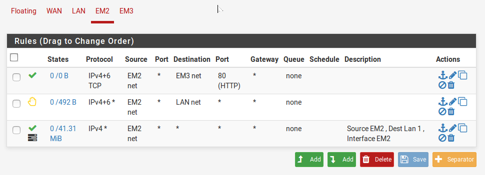 |
|---|
| Image-4:Rules on Lan-2(em2) interface |
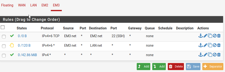 |
|---|
| Image-5:Rules on Lan-3(em3) interface |